My long term plan is to show temperature and humidity on screen, add the ability to turn my fan on via infrared LEDs, and connect it all up to Home Assistant.
In the short term, I want to get the basics working, being able to upload code, with a temperature display if I can.
The device
The device I have was from an AliExpress listing. I thought the screen would be great for quick feedback, and I think that is definitely true here.
Bare board Boxed device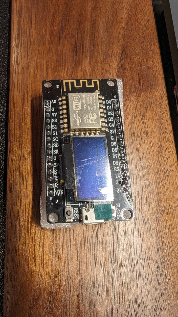
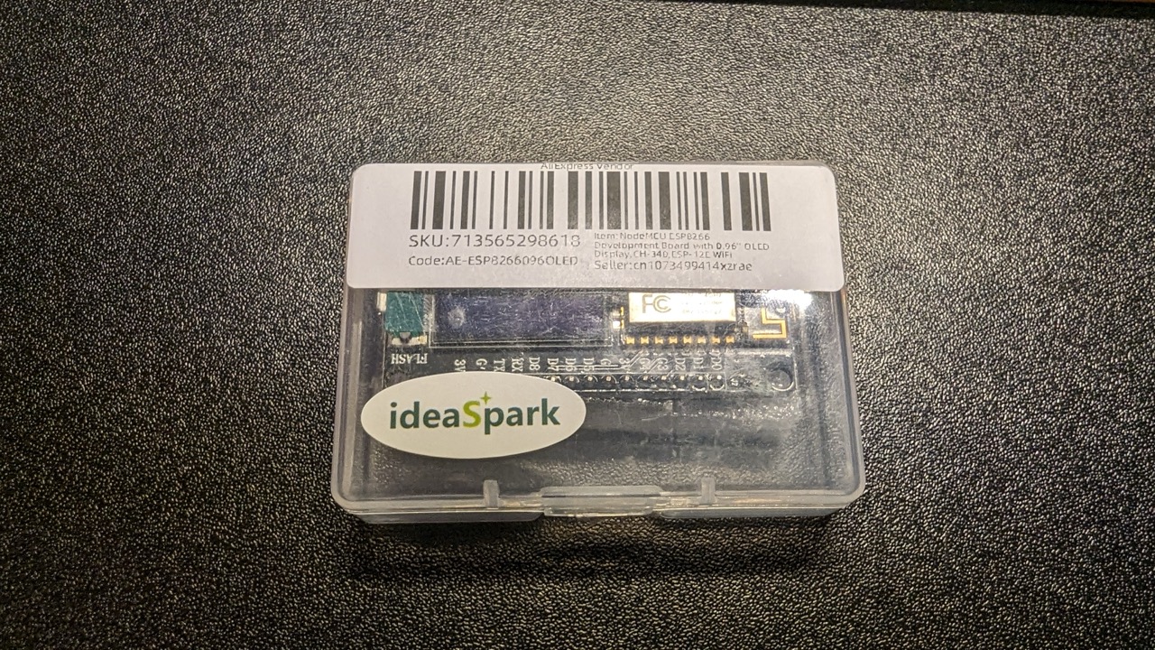
I bought a few of these boards from AliExpress. I have several others but this seemed like a great starting point.
Difficulties and solving them!
- Where the hell do I get the info about this random AliExpress board?
- What are the pinouts, and how can I put stuff on screen?
- How can I connect the temperature monitor and use it?
Well, long story short, I managed to find the AliExpress listing. This contained a lot of vital information:
| Spec | Detail | Notes |
|---|---|---|
| Memory (RAM) | 128KB | |
| Storage | 4MB | |
| SRAM | 64KB | |
| Clock speed | 80MHz |
And some really important pinout info (ESP8266 -> OLED), combined with ESP8266 info that I managed to glean:
| ESP8266 Pin | OLED Pin | Notes |
|---|---|---|
| VCC (3.3v) | VCC | |
| GND | GND | |
| D6 (GPIO12) | Screen Clock | In ESPHome, this is mapped to the i2c sda line |
| D5 (GPIO14) | Screen Data Line | In ESPHome, this is mapped to the i2c scl line |
I also managed to find some other valuable information:
- Don’t connect anything external to D5. This makes the device not boot properly (probably because the screen is on that line)
- Don’t connect anything permanently to D8. My device wouldn’t boot when I connected it up. I believe from reading online that this is because D8 can be used to select SD Card on bootup on the ESP8266.
Other pinouts that I manage to find and document.
| Board marking | Pin | GPIO | SPI | I2C | UART | Power | System | SD Card |
|---|---|---|---|---|---|---|---|---|
| D0 | GPIO16 | GPIO16 | - | - | - | - | WAKE | - |
| D1 | GPIO5 | GPIO5 | - | SCL | - | - | - | - |
| D2 | GPIO4 | GPIO4 | - | SDA | - | - | - | - |
| D3 | GPIO0 | GPIO0 | - | - | - | - | FLASH | - |
| D4 | GPIO2 | GPIO2 | - | - | - | - | TXD1 | - |
| D5 | GPIO14 | GPIO14 | HSCLK | - | - | - | - | - |
| D6 | GPIO12 | GPIO12 | HMISO | - | - | - | - | - |
| D7 | GPIO13 | GPIO13 | HMOSI | - | - | - | - | - |
| D8 | GPIO15 | GPIO15 | HCS | - | - | - | - | - |
| D9 | GPIO3 | GPIO3 | - | - | RXD0 | - | - | - |
| D10 | GPIO1 | GPIO1 | - | - | TXD0 | - | - | - |
| A0 | ADC0 | ADC0 | - | - | - | - | - | - |
| - | VIN | - | - | - | - | VIN | - | - |
| - | GND | - | - | - | - | GND | - | - |
| - | 3.3V | - | - | - | - | 3.3V | - | - |
| - | EN | - | - | - | - | - | EN | - |
| - | RST | - | - | - | - | - | RST (Reset) | - |
| CLK | GPIO6 | GPIO6 | SCLK | - | - | - | - | - |
| SDD | GPIO7 | GPIO7 | MISO | - | - | - | - | - |
| SD1 | GPIO8 | GPIO8 | MOSI | - | - | - | - | - |
| SD2 | GPIO9 | GPIO9 | - | - | - | - | - | SDD2 |
| SD3 | GPIO10 | GPIO10 | - | - | - | - | - | SDD3 |
| CMD | GPIO11 | GPIO11 | - | - | - | - | - | SDCMD |
| - | CH_PD | - | - | - | - | - | CH_PD | - |
| RSV (Do not use!) | - | - | - | - | - | - | - | - |
My setup
I installed ESP Home through Home Assistant. I have my HA and my IoT networks on separate networks so I am using static IPs for now - I know there are ways to use mDNS to make discovery work properly, but I haven’t worked it out yet in my router.
And here is my setup:
esphome:
  name: test-esp8266-ideaspark
  friendly_name: test_esp8266_ideaspark

esp8266:
  board: esp01_1m

# Enable logging
logger:

# Enable Home Assistant API
api:
  encryption:
    key: fakekey

ota:
  password: fakepassword

wifi:
  ssid: !secret wifi_ssid
  password: !secret wifi_password

  manual_ip:
    static_ip: 192.168.107.231
    gateway: 192.168.107.1
    subnet: 255.255.255.0

  # Enable fallback hotspot (captive portal) in case wifi connection fails
  ap:
    ssid: "Test-Esp8266-Ideaspark"
    password: fakepassword

captive_portal:

# Here are the important bits for a test
i2c:
  sda: GPIO12
  scl: GPIO14

font:
  - file: "gfonts://Ubuntu+Mono"
    id: ubuntu_font
    size: "16"

sensor:
  - platform: dht
    pin: GPIO5
    temperature:
      name: "Temperature"
      id: "temp"
    humidity:
      name: "Humidity"
      id: "humidity"
    update_interval: 60s

display:
  - platform: ssd1306_i2c
    model: "SSD1306 128x64"
    reset_pin: GPIO0
    address: 0x3C
    lambda: |-
      it.printf(0, 18, id(ubuntu_font), "%s", String(id(temp).state).c_str());
      it.printf(0, 40, id(ubuntu_font), "%s", String(id(humidity).state).c_str());
And here is how it looks in all it’s glory:
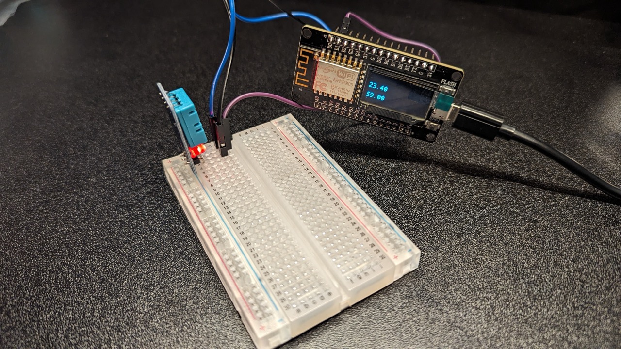
Example working
References
- https://www.electronicshub.org/nodemcu-esp8266-oled-display/ - Great for Pinouts and a similar experience with the display.
- https://randomnerdtutorials.com/esp8266-pinout-reference-gpios/ - A more formal pinout reference
Lots of ESPHome documentation
- https://esphome.io/guides/automations.html#script-wait-action
- https://esphome.io/components/display/index.html#formatted-text
- https://esphome.io/components/display/fonts#display-fonts
- https://esphome.io/components/sensor/dht
- https://esphome.io/guides/configuration-types#config-pin
Temperature sensor
Random other ones
- https://blog.balena.io/build-a-raspberry-pi-powered-train-station-oled-sign-for-your-desk/ - I remembered this and it linked to a cool font that I thought would work well on the screen, but unfortunately it doesn’t look great at this tiny screen size.